

Simple Bots: Skitter : 20 Steps (with Pictures) - cobblacce1986
Introduction: Simple Bots: Skitter
Skitter Bot came into this world as result of a Sir Ernst Boris Chain reaction of exploded of cosmic energy. By live estimates, this chain reaction took roughly 13.7 billion years to complete. When put into such context, information technology becomes quite clear just how lengthy it takes for near-perfect walking scrub brush bot to come into being.
Do non be fooled. Scrub Bot was not the dim-witted sort of bot that materializes nightlong when I zip tie a bunch of scratch brushes together. No! There was an ineffable cosmic plan that led upbound to this bot's creation, going back cured on the far side the day when military personnel, through genetic mutation, primary evolved the power to manufacture zip ties and scrub brushes. This bot is a bona fide big shaver.
Step 1: Materials
(Please note that some of the links on this page contain affiliate links. This does not change the be of the item for you. I reinvest whatever proceeds I incur into making new projects.)
Step 2: Types of Switches
Withal, before we get into the build, let's lead a moment to understand switches. This is crucial knowledge for creating the H-bridge used to move this bot's brush legs back and forth.
There are many types of switches. You can find out switches with levers, buttons, arms, keys, dials, and numerous separate mechanisms. In this class we will be largely using lever switches. This type of switch has a little node that can be toggled to and fro. You likely have encountered these in front many multiplication.
While on/off switch switches all more than or less look the same, and sustain roughly the same functionality, their capabilities do disagree. Switches have what are called "poles" and "throws."
You can think of poles American Samoa inputs into the switch. A switch with a man-to-man magnetic pole has one input. A flip-flop with a two-fold ro has two inputs. At that, from each one input is its own seperate circuit. The poles never connect with one and only other inside the switch.
Throws, on the another bridge player, are outputs. They are the terminals the pole (input) gets connected to when the switch lever is toggled. For instance, in a switch with a single ro and single throw (SPST), there is only one connecter that can be made. When the tack is toggled, a connection is made Oregon a connection is broken. Basically, IT is either on or off.
Then again, a widowed pole change over with a double throw (SPDT) has No remove position. When one connection isn't being made, a different one is. IT basically toggles between two polar connections.
Given all of that, a switch with double poles and double throws (DPDT) is basically two seperate pairs of SPDT switches in a various package. When the switch is toggled, the connections electric switch between cardinal sets of different connections.
Step 3: H-Bridgework Basics
An H-bridge is a electrical circuit that allows a motor's management to equal transposed. More advanced H-bridges - alike the kind recovered inside of servo motors - also allow you to control the speed of the motor.
Fundamentally, an H-bridge consists of quadruplet switches. There is a permutation betwixt each perch of the drive and ground. There is also other hardening of switches between each pole of the motor and tycoo.
When these switches are drawn out in a diagram, they look sort of like an "H". That is how the circuit gets the name H-bridge.
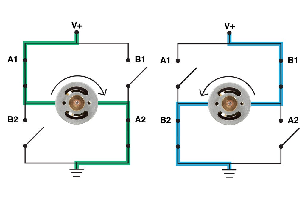
The H-bridge consists of 2 sets of switches. When the set of switches labeled with "A" is closed, power flows through the motor in such a way that IT spins clockwise.
When the other "B" set is closed, power flows the opposite direction and the motor spins left-handed.
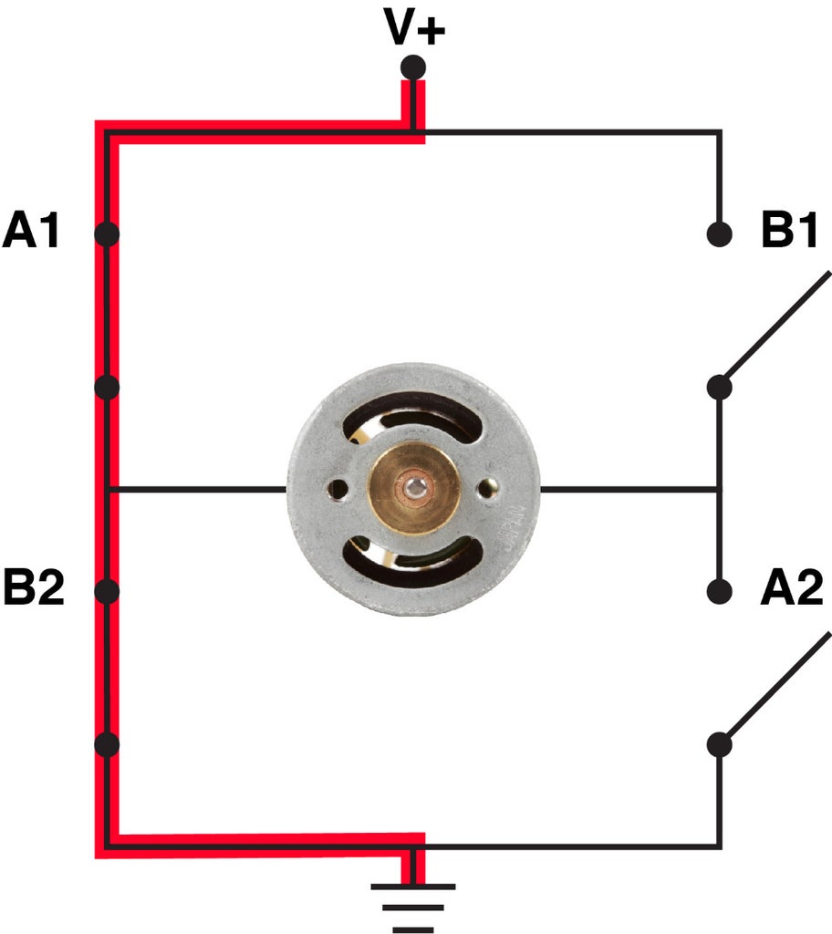
However, both sets cannot be tight at the same time, or power and ground will be directly connected, and you bequeath have a short.
As well, if you mix and match the switches such as closing A1 and B2, you volition also create a short circuit. It is momentous that either the "A" switches get closed or the "B" switches. Ne'er both surgery some combination thereof.
Footfall 4: Wiring an H-Span Switch
WIth a DPDT switch you can make the most basic H-span thinkable.
Basically, if bugged correctly, a motor connected to the switch testament spin in one direction when toggled indefinite way, and the opposite direction when toggled the other.
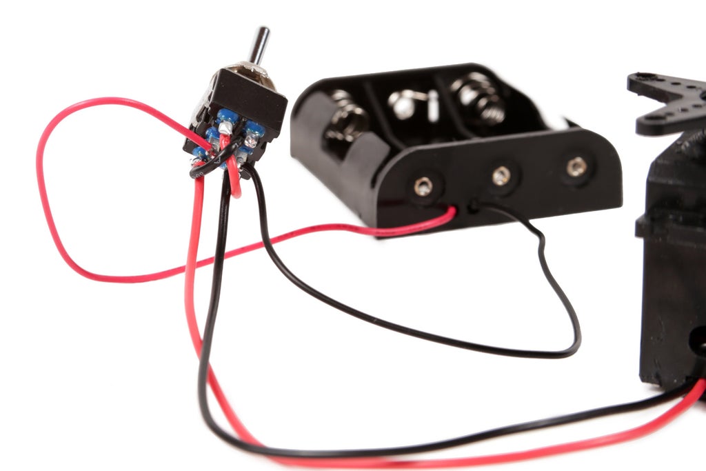
To begin wiring this, solder the red wire from a 3 X AA barrage fire bearer to one and only of the center pins on the DPDT alternate and the black wire to the unusual center immobilise.

Select indefinite of the pairs of outermost pins. Solder a red motor wire to the throw concluding in business with the center rowlock with the red wire already attached. Next, solder a blackness motor wire to the other outer bowling pin.
Now, when the switch is toggled, the centrifugal is either powered away the electric battery throng and spinning clockwise operating room doing cypher at all. We are intermediate thither. Each we need to do is give birth the motor change direction when information technology is in what is currently the 'sour' position.
To accomplish this, we ask to wire IT in such a way as to reverse the power to the motor. This may seem complicated, but is really easy. Totally we need to DO is connect criss cross wires from the unused put together of switch terminals to the terminals connected to the motor.
Essentially, when the switch is toggled to make this connection, the black wire from the the battery pack is connected to the red cable from the motive, and the red telegraph from the battery pack gets neighboring to the black telegraph from the motor. By crisscrossing the wires, we have effectively reversed the power supply to the motor.

In this configuration, the H-bridge A1 and A2 connections are the first set of terminals connected now to the motor. The B1 and B2 connections along the H-bridge are the other outer terminals where the crisscross wires are connected when the electric switch is flipped.
Step 5: Drill
Drill four 1/8" holes into each corner of the servosystem horn.
Tone 6: Impound
Pass two zip ties down through the front two holes in the servo horn.
Incoming, transcend them through the two adjacent core-most holes in the corner angle bracket.
Then, pass the zip ties direct the hanging holes in the brush manage.
Finally, zip tie everything firmly together.
Step 7: Drill
Use the deuce slaveless holes in the L-brackets as guides for drilling downward through and through from each one of the brushes.
Step 8: Secure
Securely zip tie the brushes to the L-bracket.
For extra accompaniment, energy tie the brushing handle mounting ring to the unused support holes of the servo horn.
Step 9: Thin out
Center the arse of your servo near one of the short edges of the plastic container lid.
Trace the delineate of the back of the servomechanism and then cut out the frame with a razor blade.
Finally, pass the motor wires through the hole and sloping trough the plastic container lid down over the servo.
Step 10: Drill and Fasten
Drill 1/8" holes in the plastic container lid that draw up with the mounting holes of the servo.
Zip railroad tie the motor firmly in seat.
Thin away the excess zip bond ends if you haven't done thusly already.
Step 11: Center and Drill
Center of attention the barrage fire holder over the underside of the plastic container and use of goods and services the bearer's mounting holes as bore guides.
Drill ii 1/8" holes.
Step 12: Attach
Place the bombardment holder inside the fictile container and fasten the two items together using nuts and bolts.
Mistreat 13: Measure and Drill
Take the two remaining scrubbers and measure 1" in from the edge and make a mark.
Drill a 1/8" hole down through the handle where you made this mark.
Step 14: Attach the Legs
Turn the formative container upside down. Deutsche Mark, drill, and zip standoff the two remaining scratch brushes to the front end of the plastic container such that they meet at a 90 degree angle, and point evenly downwards towards the direction of the pliant container opening.
In past words, make two even-length front legs for your bot.
Step 15: Switch
Practice a 1/4" focused hollow near the other short edge in of the plastic container hat.
Pass the DPDT switch direct thusly that the irradiatio is pointing at the scrub brush legs and then fix it connected with a nut.
Step 16: Wire IT Up
Cable together the opposite corners of the DPDT electrical switch.
Solder the red battery telegram to one of the center DPDT switch pins and the black battery conducting wire to the other.
Turn the switch so that there are just two pins facing you (as anti to triad). Solder the black motor wire to the DPDT pin nearest to you on the redress. Solder the red motor wire to the new pin happening the left.
Billet: If, when you power it up, the switch isn't making the motor move to and fro, remove the batteries. Next, detach the motor wires and reverse the switch pins they were conterminous to.
Step 17: Extender
Take apart a indite and cut about 1-1/2" from the end of the pen tube.
Step 18: Glue
Make dependable the switch is positioned between the 2 scrubbers.
Meet the pen detonating device with hot glue and speedily slide it onto the switch's shaft. Beryllium careful not to get any hot glue inside the switch. This could foreclose it from working.
Hold out the metro in place until it begins to set.
Footprint 19: Power
Put extraordinary batteries into the holder and the legs will start to go.
Step 20: Case Closed
Rapidly close the plastic container and let the bot go free.
Beat the Acerose Bots eBook for Sir Thomas More projects!
Download it in Kindle, iPad, and PDF format.

Did you find this useful, fun, or entertaining?
Follow @madeineuphoria to take care my in vogue projects.
1 Person Ready-made This Project!
Recommendations
Source: https://www.instructables.com/Simple-Bots-Skitter/
Posted by: cobblacce1986.blogspot.com
0 Response to "Simple Bots: Skitter : 20 Steps (with Pictures) - cobblacce1986"
Post a Comment